 |
 |
 |
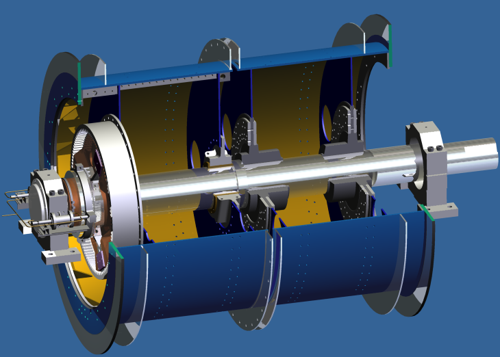
1.Single rope hoist structure-1
|
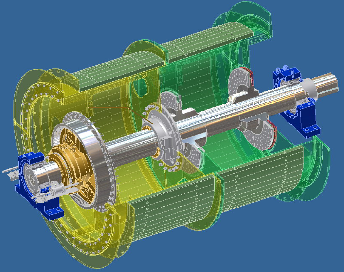
2.Single rope hoist structure-2
|
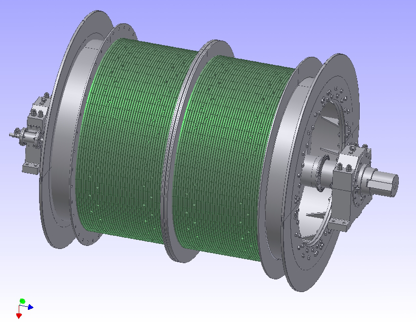
3.Single rope hoist structure-3
|
 |
 |
 |
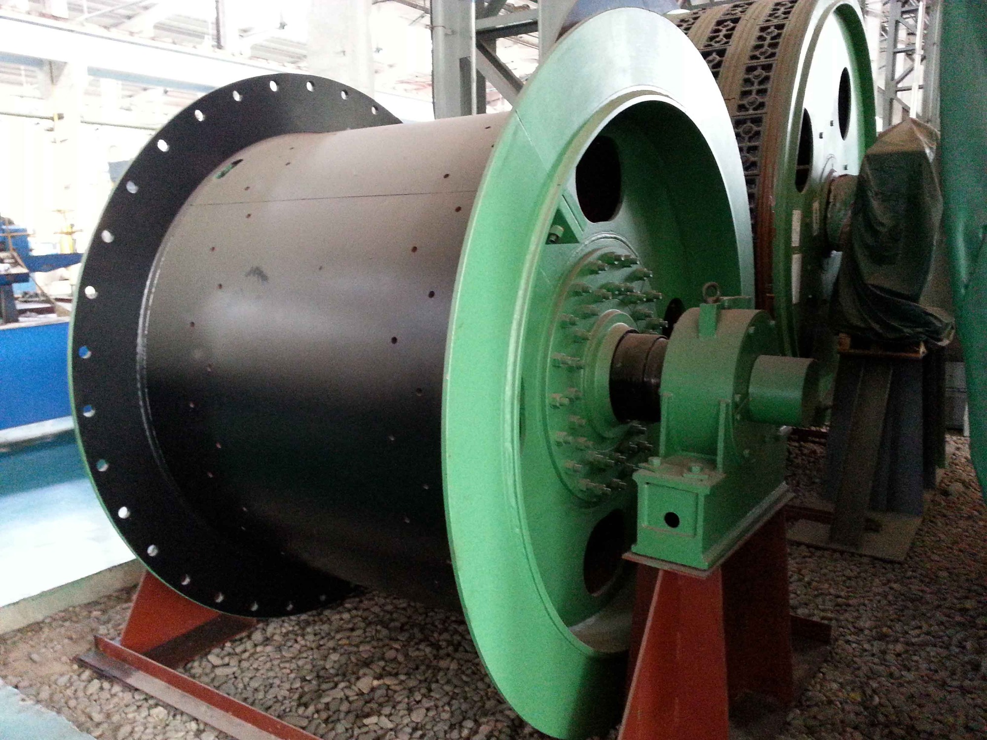
| 4.Single rope winding mine hoist-1 |
5.Single rope winding mine hoist-2 |
6.Single rope winding mine hoist-3 |
Structural Description Of Friction Drive Hoist
1.Main shaft device
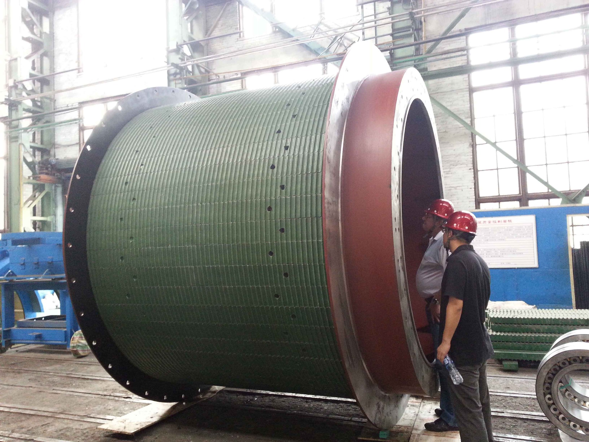
The main shaft device is the working mechanism of the hoist and the main bearing component of the hoist. It bears all the torque of the hoisting and lowering loads, as well as the tension of the wire rope on both sides of the friction wheel. It mainly consists of main shaft, friction wheel, rolling bearing, bearing chock, bearing cap, bearing beam, friction liner, fixing block and pressing block.
2.Friction wheel
The friction wheel is made of integral low alloy steel and fully welded structure. The part is welded by shell, left and right spokes, left and right hub, supporting ring and baffle plate. For large hoist (diameter greater than or equal to 2.8m), supporting ring is welded inside the shell to strengthen the stiffness of the whole shell, and no supporting ring is added for small multi-rope hoist (diameter less than 2.8m), which is simple in structure and convenient in manufacture.
3.Brake disc
Brake discs for small lifts mostly use non-removable welded brake discs (also known as dead brake discs), that is, brake discs are welded at the end of the drum. For large-scale hoist, the detachable combined brake disc is generally used, that is, the brake disc is made into two halves, and is installed on the friction wheel in pairs. The high-strength bolts for the friction wheel and the brake disc are connected by large plane friction. There is a matching stop between the brake disc and the friction wheel for radial positioning, and the key for axial positioning between the two halves of the brake disc.
4.Main shaft
Main shaft is one of the main parts of the main shaft device. It bears the self-weight of the whole Main shaft, external load and transfers all the torque. It is forged with high quality medium carbon steel or low alloy steel. One or two flanges are forged directly on the shaft and connected to the friction wheel by high strength bolts. The main bearing is a supporting component which bears the self-weight of the whole main shaft and all loads on the wire rope. It is composed of rolling bearing, bearing cap, bearing chock, bearing end cap and other components.
5.Connection Mode of Friction Wheel and Spindle
Using double flange connection,above JKM (D) 4 *4 of the series of products used in connection mode: in the transmission side friction wheel spoke and spindle flange using high-strength bolt double flange, double splint friction surface connection, by splint friction wheel and spindle connection, but also by friction transmission moment. The inner holes of the two hubs and the outer flange garden of the main shaft are fitted with small clearance. The friction wheel and the main shaft of the hoist with this structure are assembled in the factory only on trial. After passing the inspection, they are separately disassembled and shipped, and then assembled formally according to the requirements of the drawings on the spot.
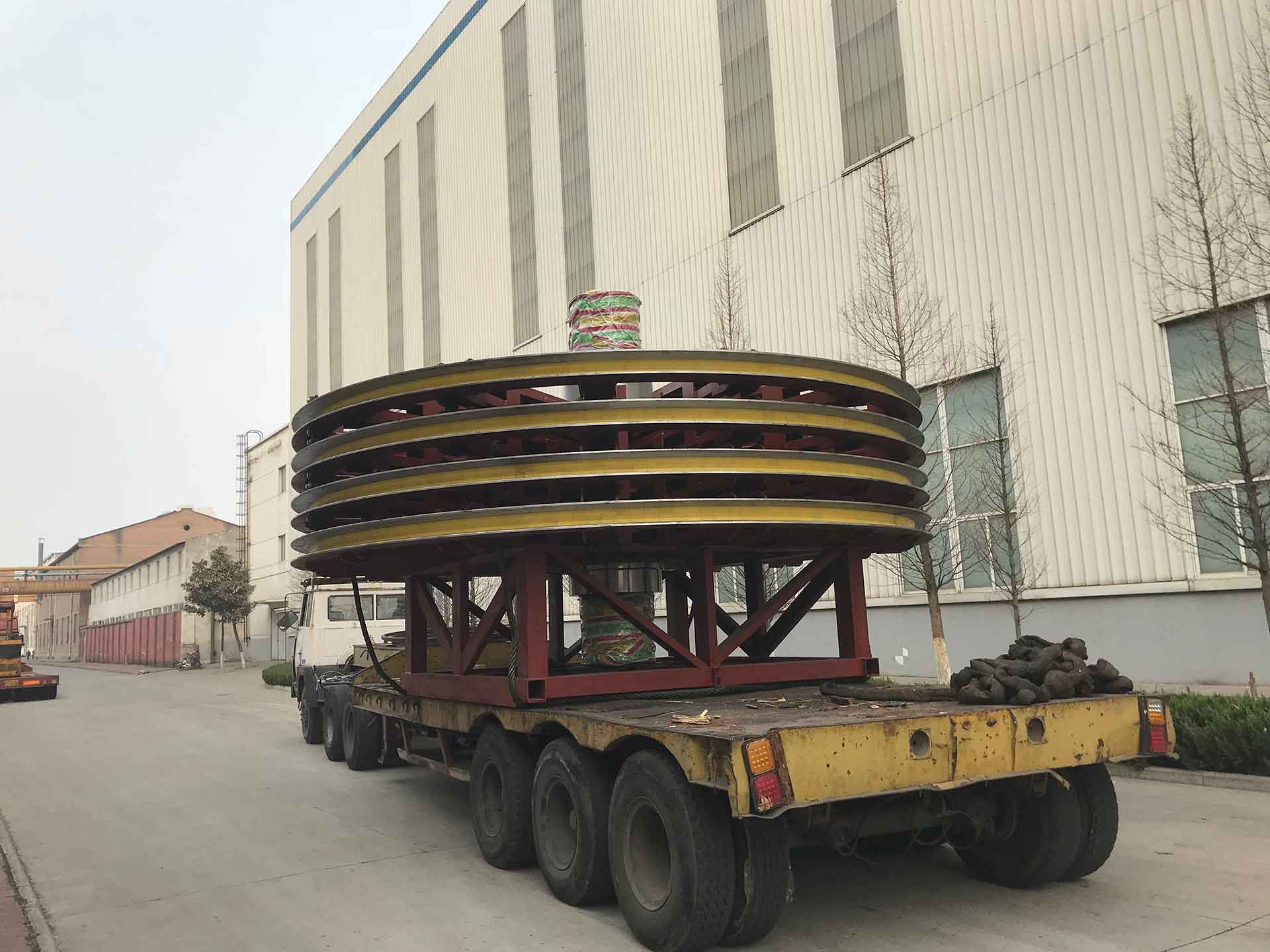
6.Structure of Skywheel Device (Guide Wheel Device) of Multi-rope Friction Hoist
Each set consists of several separate wheels, one of which is connected with the axle by a flat key, called a fixed wheel. When the steel rope moves, it drives the fixed wheel to rotate, and the fixed wheel drives the crankshaft to rotate together. The rest of the wheels are swimming with the crankshaft, called a cruise wheel. There are four half axle bushes (copper bushes) between each hub and axle of the wheel. There are 0.2-0.5 mm axial clearances between the four wheels. When the linear speed of each rope is not exactly the same, the wheel and axle can rotate freely and relatively. The flange groove is equipped with polyvinyl chloride or nylon liner to protect the steel rope from friction between the steel rope and the cast steel flange, thereby improving the service life of the steel rope.Both rim and hub are welded by casting steel and spoke (channel steel). Generally speaking, the wheel of the skyscraper device is integral. The wheel body of the skyscraper device of a large hoist can be divided into two halves. It is called a split skyscraper. The two ends of the skyscraper device are supported on the cast steel bearing seat by ball-oriented roller bearings.
On the premise of overall transportation, the guide wheel device adopts integral casting and welding structure for both the swimming wheel and the fixed wheel. The hub and rim are cast steel, and the spoke is channel steel. After welding, the guide wheel is annealed and processed as a whole. Considering the convenience of replacing bearing bush for maintenance, there is more disassembly space for replacing bearing bush.
7.Others
The structure of guide wheel device adopts eccentric arrangement.
The guide axle is forged entirely with medium carbon alloy steel.
Imported (or domestic) spherical roller bearings can also be installed with bearing temperature measuring elements.
In order to prolong the service life of the wire rope, the wheel flange is equipped with a wedge-shaped cushion with wear resistance and pressure resistance, and D660 (or nylon 1010) cushion is used.
1) Eccentric layout: There is more disassembly and assembly space on one side of the cruise wheel for replacing the bearing bush, so that the bearing bush can be repaired and replaced only without disassembling the whole overhead wheel device.
2) Symmetrical arrangement: Four wheels are symmetrical relative to both sides of the two bearing chocks. Once the bearing bushes need to be replaced, the whole overhead wheel device can only be dismantled.